
More than ever before 3D models have become a "physical" part of our life, how we can see in the internet with 3D services of printing.
Some people have many difficult to get a model to print... well, not only to print, but to write an scientific article, make a job, or just have fun.
With this tutorial you'll learn how to scan 3D objects to use it the way you want.
Before all, I would like to thank all friends that help me to write this tutorial mainly Bob Max of the ExporttoCanoma's blog that publish interesting posts about GIS and now are interested in SfM (like all good nerd who works with 3D).
It's impossible to forget Pierre Moulon, the developer os Python Photogrammetry Toolbox (PPT), and Luca Bezzi e Alessandro Bezzi, developers of the ArcheOS and PPT GUI.
This tutorial includes many examples and some source files that will help you to learn how works the PPT.
So, lets go!
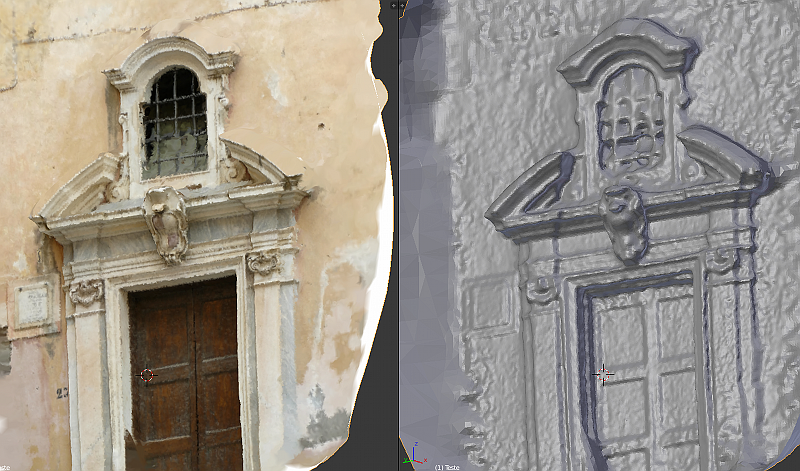
The image above show the object that we'll scan in this tutorial
How to make 3d scan with pictures and PPT GUI
First of all is necessary to download the Python Photogrammetry Toolkit on: http://www.arc-team.homelinux.com/arcteam/ppt.php
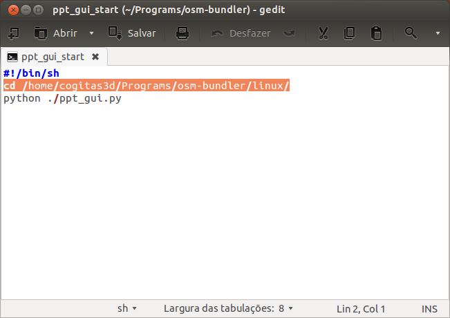
After download and unzip you have to edit the ppt_gui_start file putting the right path of the program (in orange).
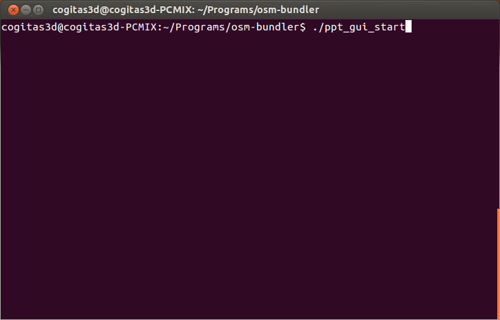
Now, if you are in Linux is only run the script edited:
$ ./ppt_gui_start

Once the program is opened, click on “Check Camera Database”.
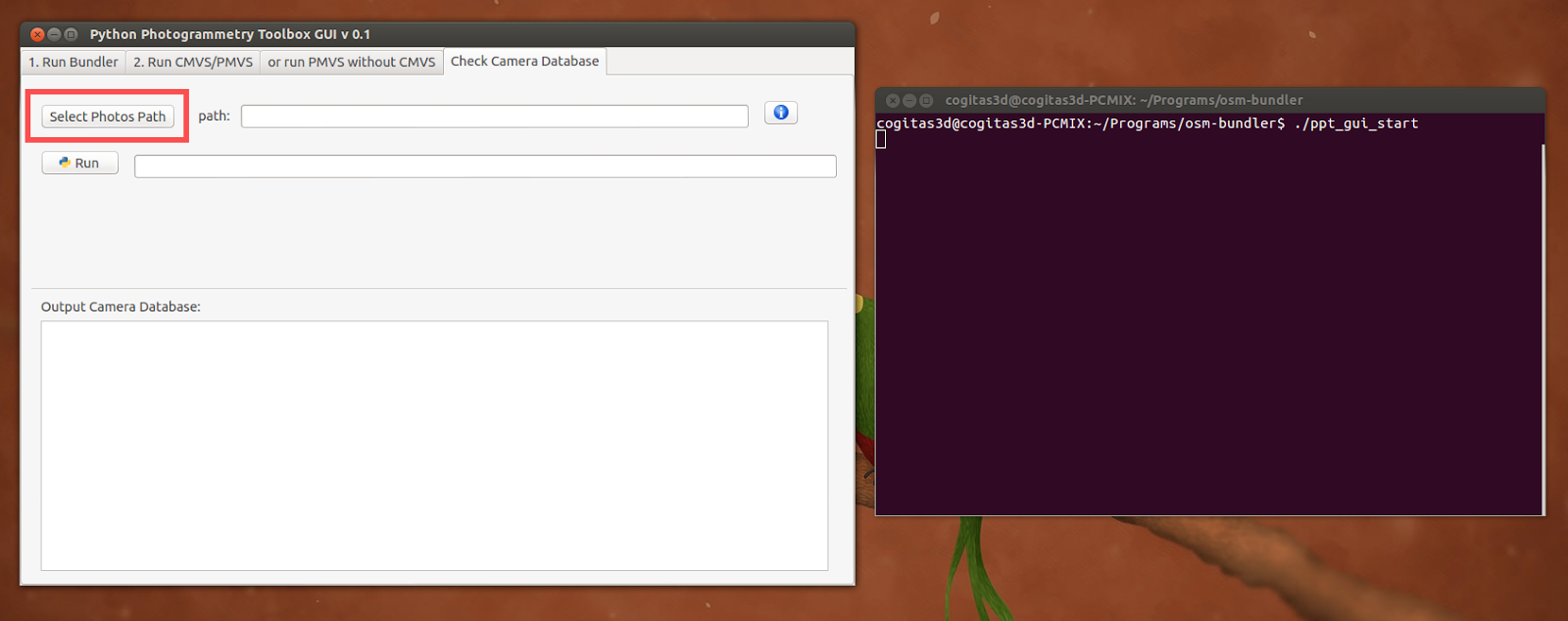
With the Terminal/Prompt by side, click in “Select Photos Path”.

Choose the path and then click on “Open”.


If all is OK, you’ll see a message in the Terminal:
Camera is already inserted into the database
If not, you can customise with this videotutorial:
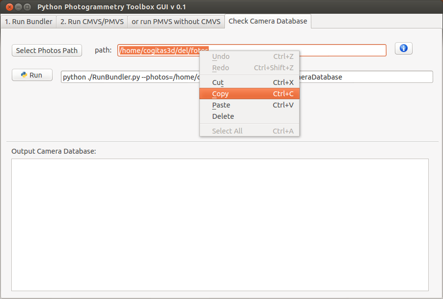
Now, make a copy of the path.
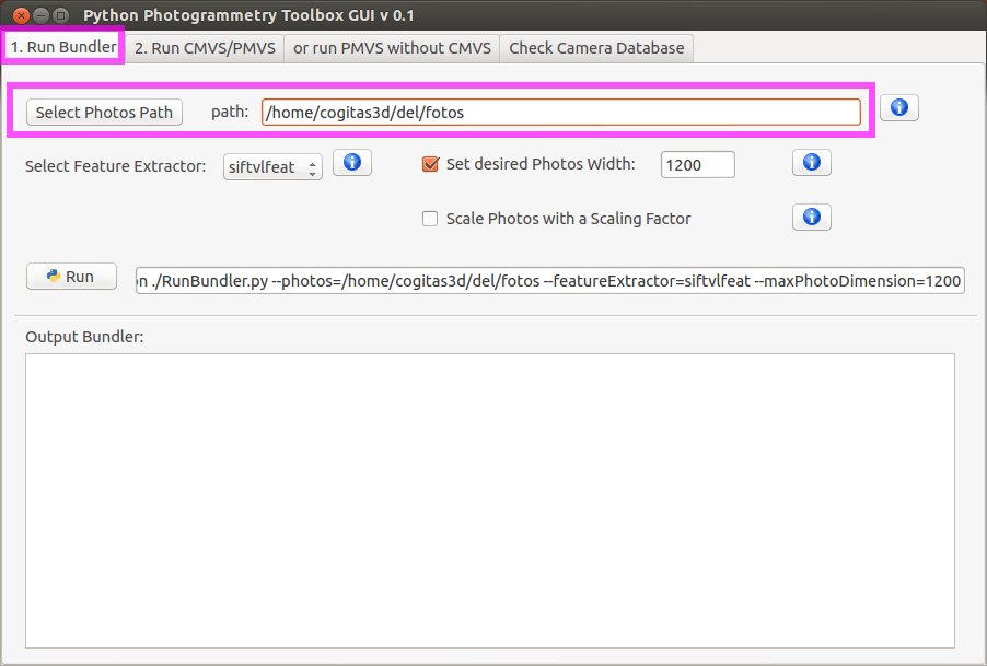
1) Go to “Run Bundler”.
2) Past at “Select Photos Path”.
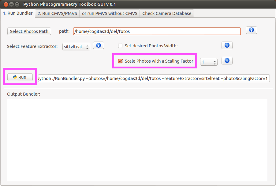
1) To make a good scan quality, click on “Scale Photos with a Scaling Factor”, by default, the value will be 1. If you have a computer with less power of processing, do not make this step (1), and go directly for the step bellow (2).
2) Click on “Run”.
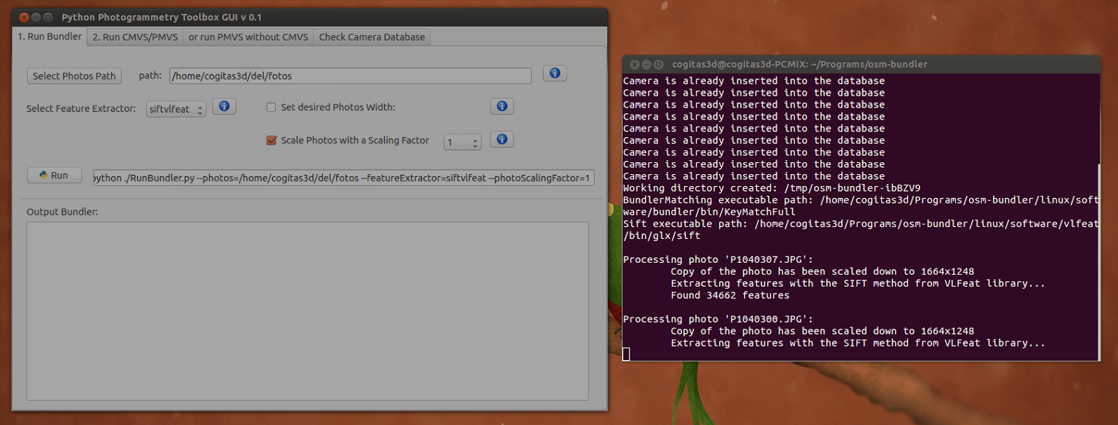
Wait a few minutes, the program will solve the point clouds.

You will know that the solve is done when in the Terminal appear the message:
Finished! See the results in the '/tmp/DIRECTORY' directory
In this case the message was:
Finished! See the results in the '/tmp/osm-bundler-ibBZV9' directory
The Nautilus will be opened to, showing the directory with the files.

OBS.: If you area really curious, you can open the Bundle directory and see the .PLY files in Meshlab. But is better wait, because this point clouds is not good to make reconstruction/convertion into a mesh.


1) Go to the “or run PMVS without CMVS”
2) Click in “Use directly PMVS2 (without CMVS)”
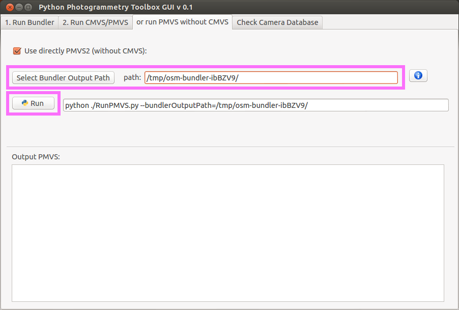
2) Click on “Run
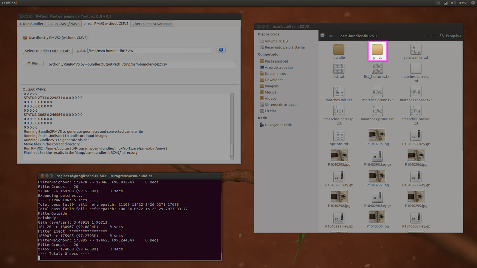
When the process is done, you’ll see a new directory named “pmvs” appear.
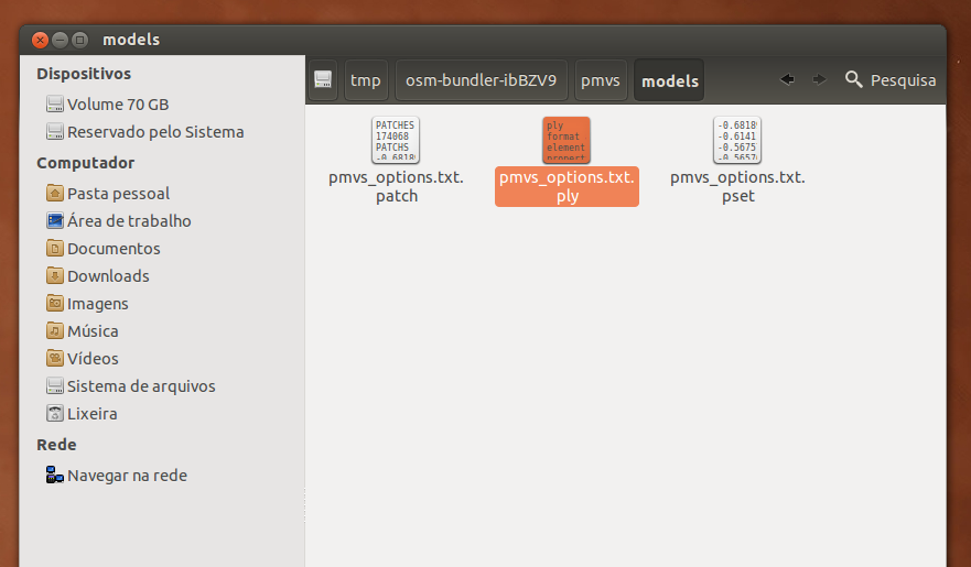
So, you have to enter in “models” and search for a file named “pmvs_options.txt.ply”. If all is OK it is the final process of solving.
OBS.: It’s a good idea copy the osm-* directory for your home, because it will be lost in the next boot, because the /tmp directory.
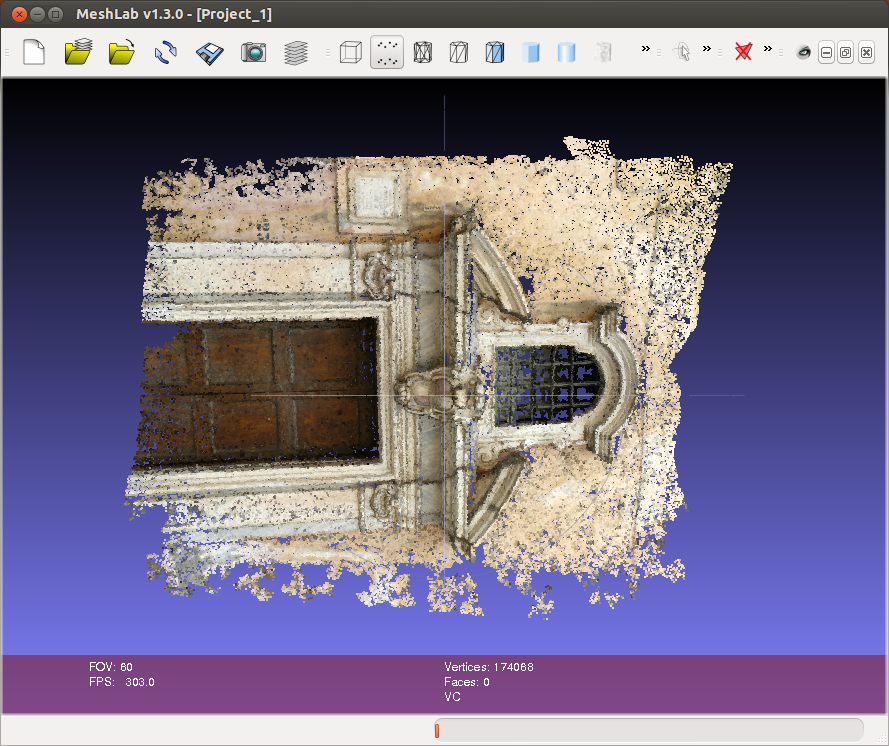
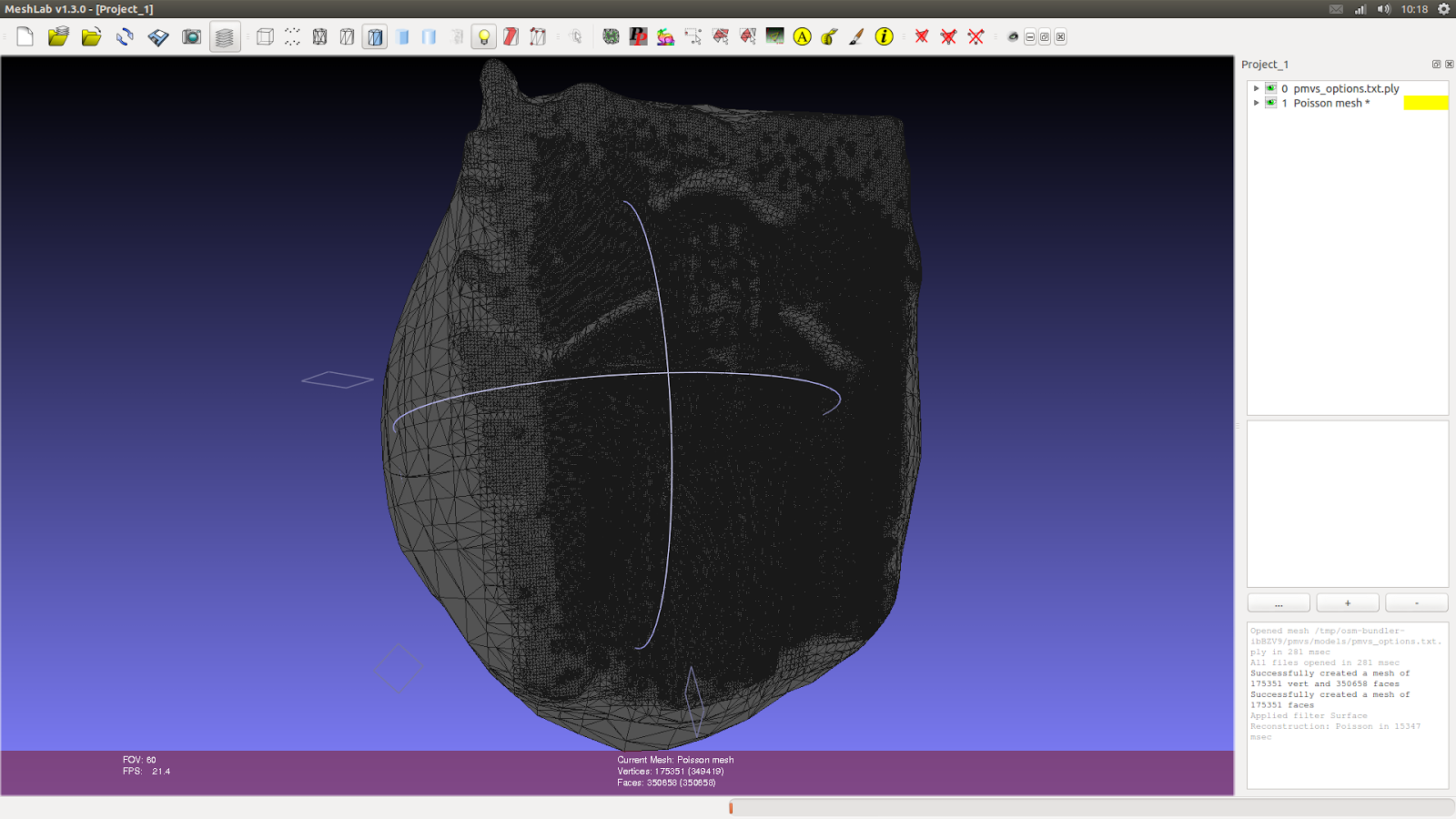
When you open the “pmvs_options.txt.ply” file in Meshlab you’ll see that the points cloud is really dense now, with almost the quality of a picture.
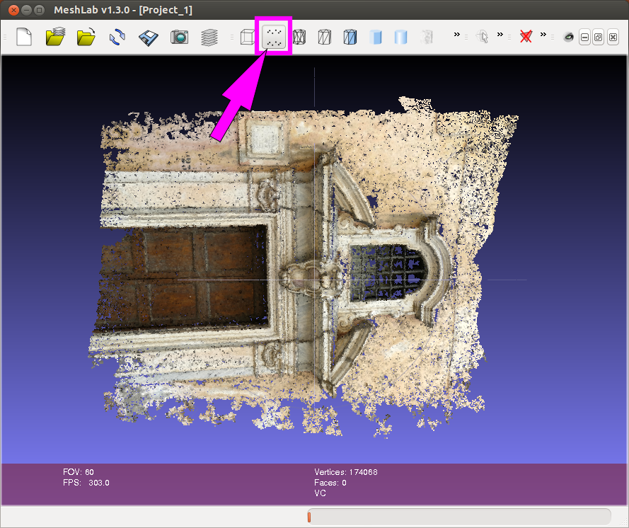
Only appear a picture or a mesh... notice that the “Points” is a way of view selected.

If you select “Flat Lines” for an exemple, the points clouds will desappear... because, obviously... it’s a --points-- cloud.

Click again in “Points” to see the points cloud and:
1) Click on “Show Layer Dialog” (A)
2) So, will appear a new element in the interface with the name of the object, in this case “pmvs_options.txt.ply” (B)
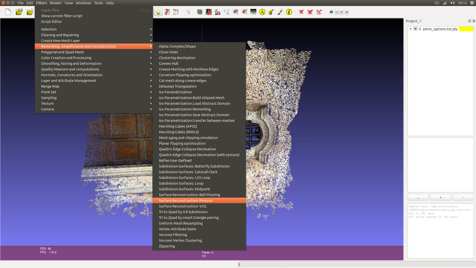
Go to “Filters” -> “Remeshing, simplification and reconstruction” -> “Surface Reconstruction: Poisson”

A new window will appear with the defaults value of “Octree Depth” and “Solver Divide”
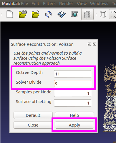
1) Change the values to:
Octree Depth: 11
Solver Divide: 9
2) Click in “Apply”
OBS: This vlues can crash the program if you computer do not have a good power of processing.

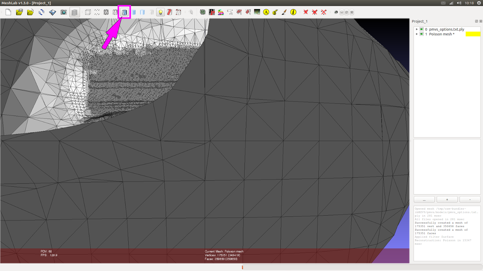
If all runs OK, you will notice two things:
1) A lot of new write points over the reconstruction.
2) A new layer in the upper right named “1 Poisson mesh *”
But, when we comeback to “Flat Line” to see the mesh, strange things can happen. In this case, the algotithm Poison created one type of ball to reconstruct the mesh.
We can see it better when we orbit away the model.

So, to make the door visible, we:
1) Come back to the “Points” view (A)
2) Orbit the scene to see the side of the door.
3) Click on “Select faces in a rectangular region”
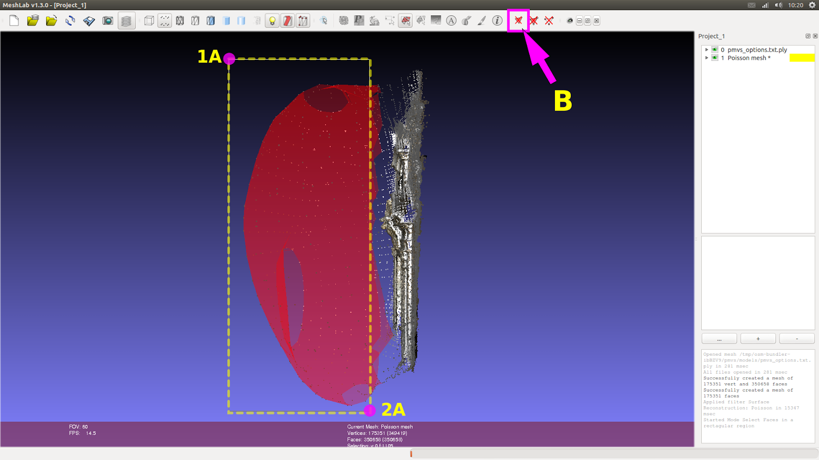
So:
1) We make a window selection on the region that will be deleted (1A-2A)
2) Click on “Delete the current set of selected faces”.
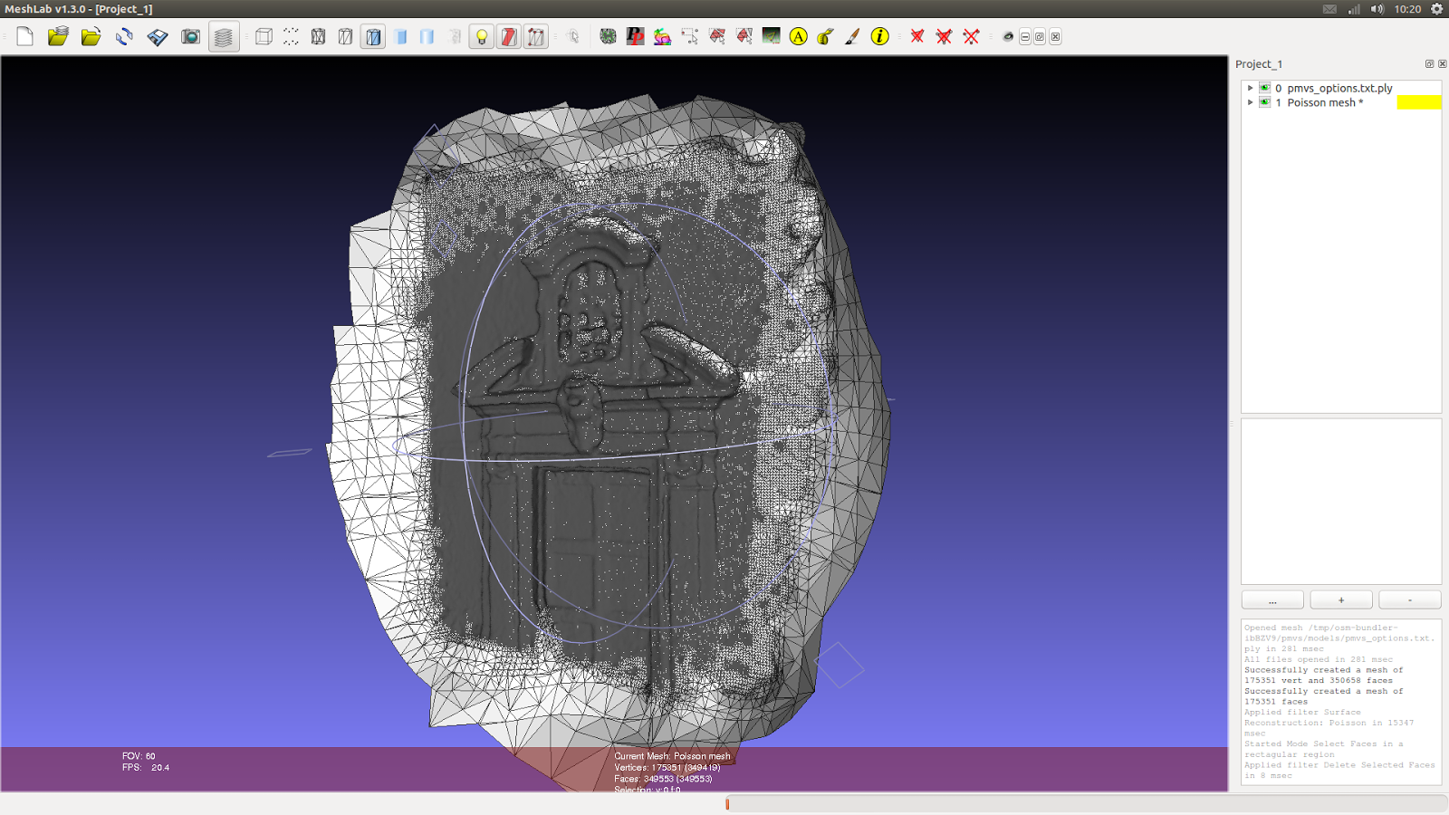
Now we can see the mesh in the correct side.
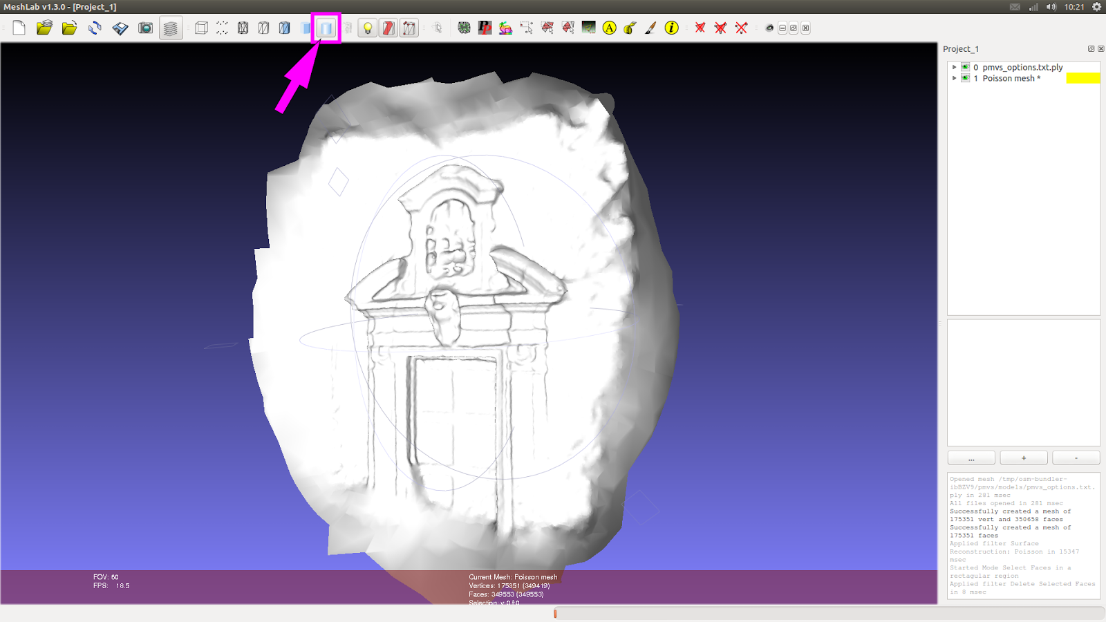
But, when we change the type of view to “Smooth”, we see the mesh write without the colors of the points cloud.
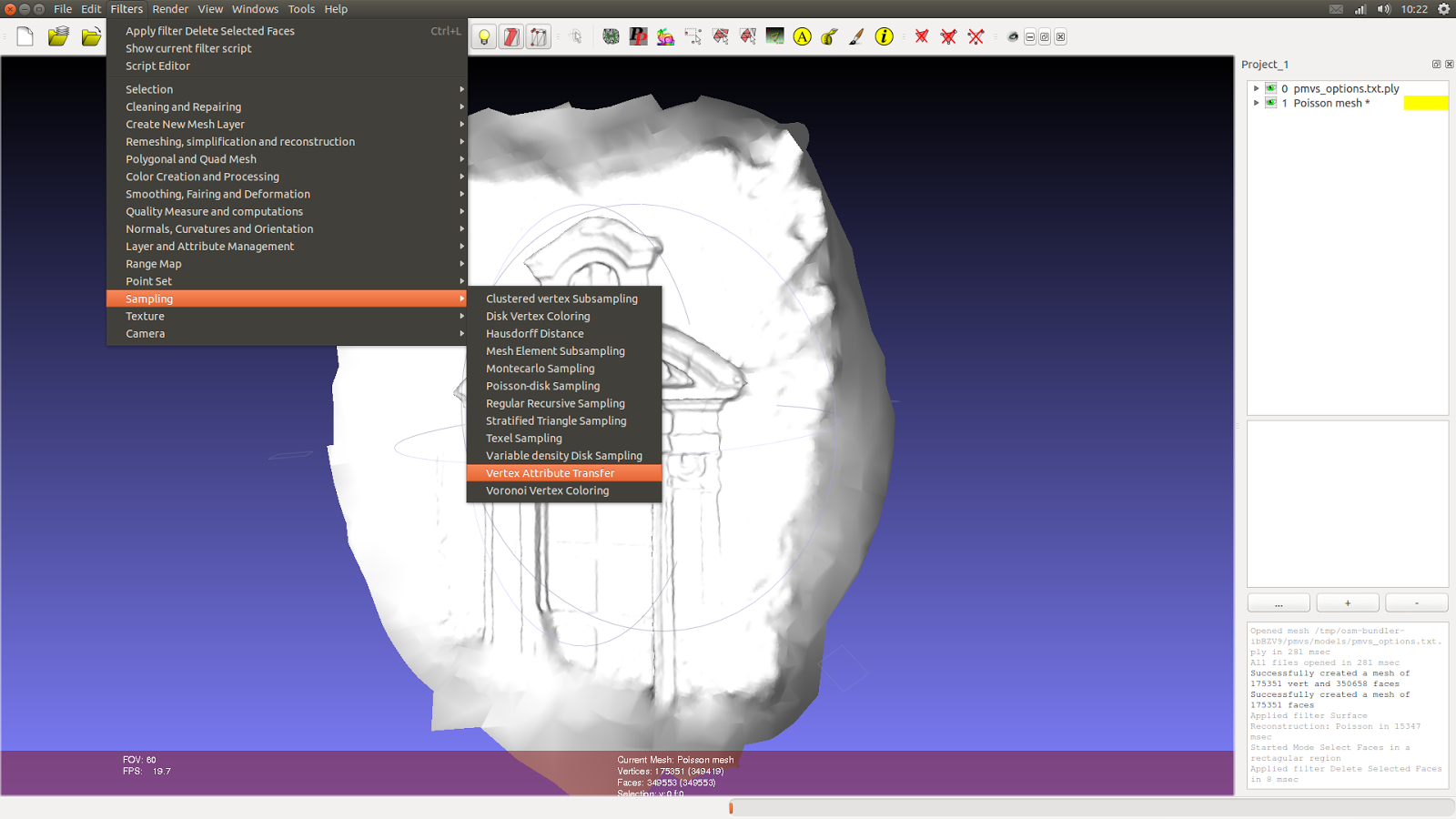
To paint the mesh with the color of the points cloud we can go to:
Filters -> Sampling -> Vertex Attribute Transfer
A substancial part of this step was learned with this video: http://vimeo.com/14783202
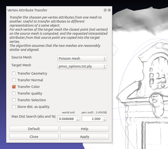
A new window will appear.

You’ll have to invert the objects, because the “pmvs_options.txt.ply” is the real source mesh, that will be the base to paint, and the “Poisson mesh” will receibe the colors, so it is the Target mesh.
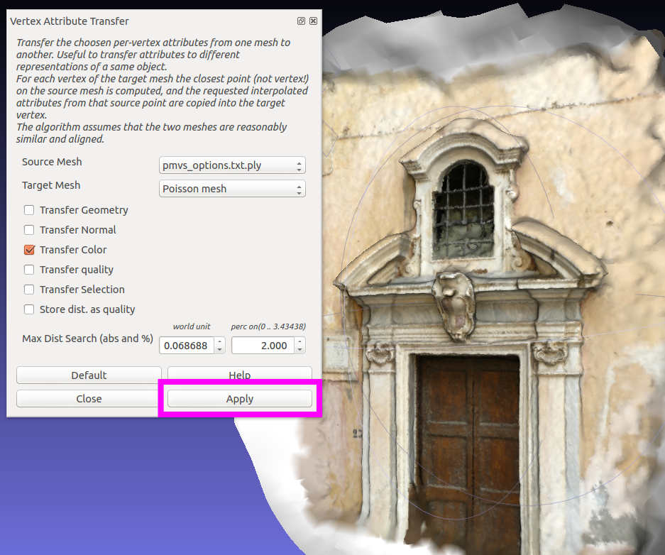
When you click on “Apply” immediatly you’ll see the mesh colored, like the image above.
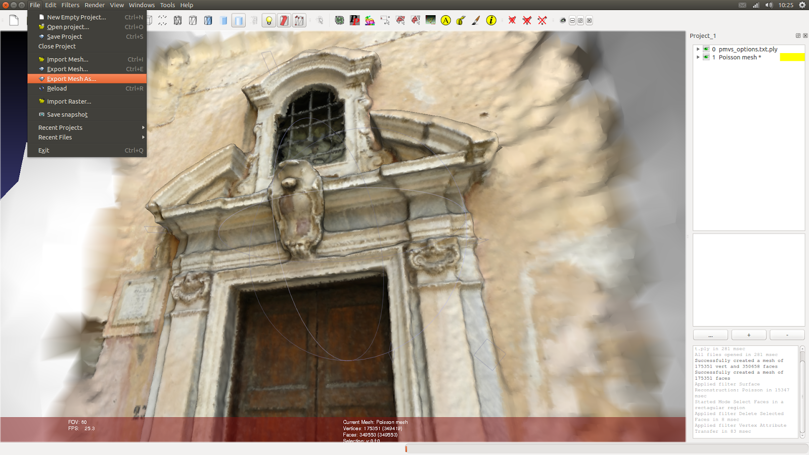
If you wanna send this mesh to other software like Blender, you can go to:
File -> Export Mesh As..
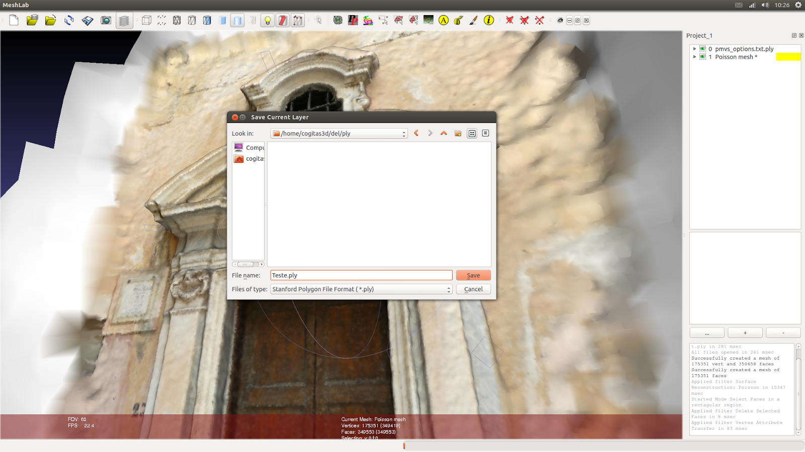
Choose a place to save the .PLY file.
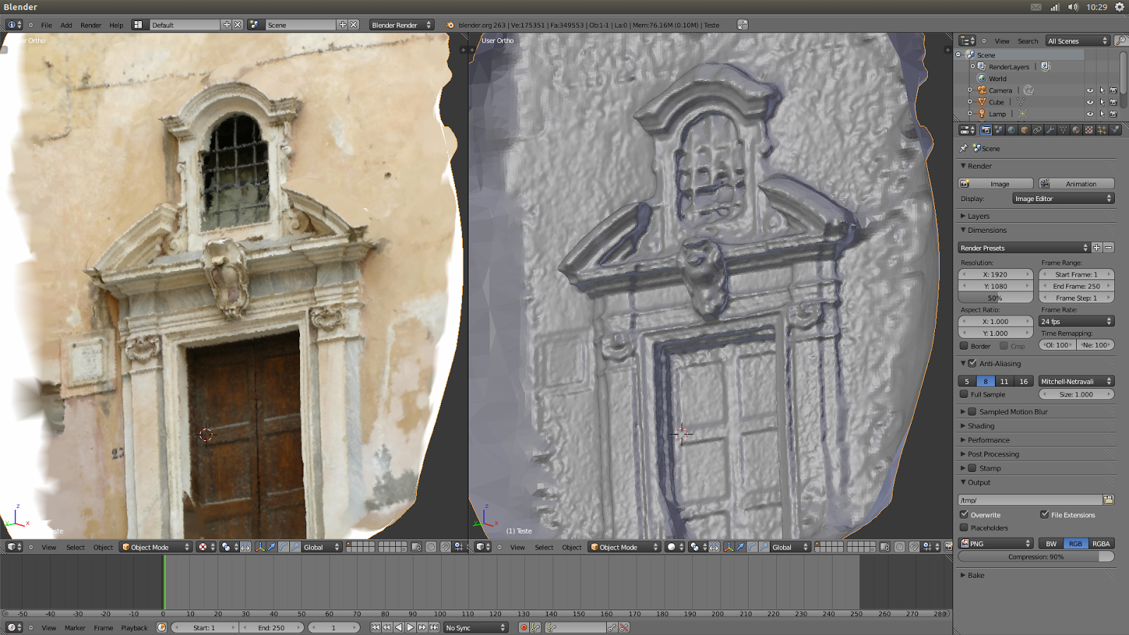
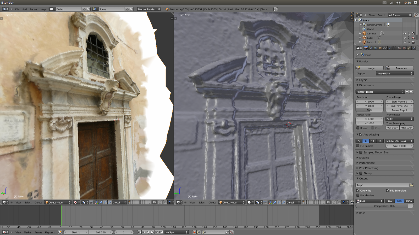
If all is OK, the mesh will be imported on Blender (or other software) perfectly.
Other examples:


If you wanna you can download a sequence of pictures of Taung Child (anim. above) to make your own test here:
And see if match with the final result here:
I hope it has useful to you.
A big hug and I see you in the next article!

Great job! As you mentioned in the final step you can use Meshlab to provide a colored texture to the mesh.
ReplyDeleteUsing Meshlab you now have three options to achieve it:
1) Transfer point cloud color information to the mesh (already covered in the tutorial). A good option when you have very detailed point clouds, but not very good when using sparse or incomplete point clouds.
2) Use osm-bundler camera parameters to transfer color information from raster images to the mesh.
see:
http://www.youtube.com/watch?v=iLs5IIYE4F8&list=UU70CKZQPj_ZAJ0Osrm6TyTg
3) Use osm-bundler camera parameters to create a raster texture, combining different raster images and mapping it (parametrization) to the mesh.
see:
http://www.youtube.com/watch?v=OJZRuIzHcVw
To do all this you just need to open as a project, inside meshlab, the PPT output file "bundle.out" and after that the respective "list.txt". The first file concerns to camera parameters and the second to associated raster images. After that just follow the already mentioned (and fantastic) Mr. P tutorials.
rgaidao
Hi Rgaidao!
DeleteThank you very much to help us! You ever came with a good news.
I watched the two videos and I think it's good!
A big hug!
Thanks very much for sharing this tutorial
ReplyDeleteThanks Rafa!
DeleteHow can I voxelise the mesh? E.g. to DICOM format?
ReplyDeleteHi Suvi! You can use a software called InVesalius. Link: http://svn.softwarepublico.gov.br/trac/invesalius A big hug!
DeleteIsn't that software meant for creating 3D from stack of images? I dont have a stack. I have .PLY files created with Python Photogrammetry Toolbox. InVesalius didn't open .PLY files.
ReplyDeleteI understoo now...
DeleteWell, I dont know if have some program that voxelise a mesh, but I found a way to do this and explained here:
http://arc-team-open-research.blogspot.com.br/2012/11/taung-project-recovering-missing-parts.html
A big hug!
Interesting, but maybe not exactly what I need.
ReplyDeleteMaybe my understandance of term "voxelisation" is wrong, or just different than yours.
I would like to convert polygonal file format (like .PLY) to a 3-dimensional raster (like .DICOM)
but I don't know if it is even possible (does the .PLY file contain the information needed to create a raster...)
Hello! This software looks very impressive!
ReplyDeleteI tried downloading it, but as a new user of Linux (Ubuntu 12.04 64 bit), I am still coming to grips with even the most basic of commands. Using Gedit included.
I failed to install the software in the first steps shown here. Would you have a beginners installation guide?
Hi Anonymous,
ReplyDeletethe easiest way to install PPT is to use the deb package we did. The problem is that we are working to package software for ArcheOS, the archaeological GU/Linux distribution we release (www.archeos.eu), which i s Debian based. We grant that our package works well in ArcheOS, but we do not know if it will work correctly also in Ubuntu, (but it should, being Ubuntu also a Debian based distribution). Anyway I see that you have a 64 machine, so the fastest way to work with PPT would be to compile the software. We are working to package PPT also for next version fo ArcheOS (which will be architecture-independent) and Romain Janvier already finished the package. You can find it here: https://github.com/archeos/ppt-archeos
Hi Luca,
ReplyDeleteThanks for your fast reply! I tried a Live session of ArcheOS v4 beta and it looks like a wonderful product!
I'm not an archaeologist, many of the programs that come preloaded are surplus to my needs, but I think what you are doing is really dynamic and interesting. That stated, I am very eager to really give PPT a go!
I am still having trouble installing PPT. That is (based on the instructions in this article), I am probably incorrectly "ppt_gui_start file putting the right path of the program (in orange)" and/or "if you are in Linux is only run the script edited: $ ./ppt_gui_start" :(
My installation in Windows XP:
ReplyDelete1.Python 2.7 was installed.
2.Next, PPT package was installed.
3.Python Imaging Library (PIL) 1.1.7 was installed. This was done easily with a Windows Installer obtained from the web.
4. SIP package (version 4.14.2) was installed. SIP configuration and installation was done with Visual Studio 2008 Command Prompt with commands python configure.py, nmake and nmake install.
5. PyQt4 package (version 4.9.6) was installed.
6. PyQt4 required a copy of Qt, which was also installed.
Some DLL-related problems were faced. Problems were due to a conflict between files used by PyQt4 and MATLAB. Problems were fixed by modifying the system Path variable.
I wonder what is wrong with the images when I get a message somethinng like "could not to determine the focal length in pixels"?
ReplyDeleteAnd why there is no such file as "pmvs_options.txt.ply" in the pmvs/models folder? There are only several "options-000x.ply" files (along with corresponding .patch and .pset files).
ReplyDelete